


PGMW-15
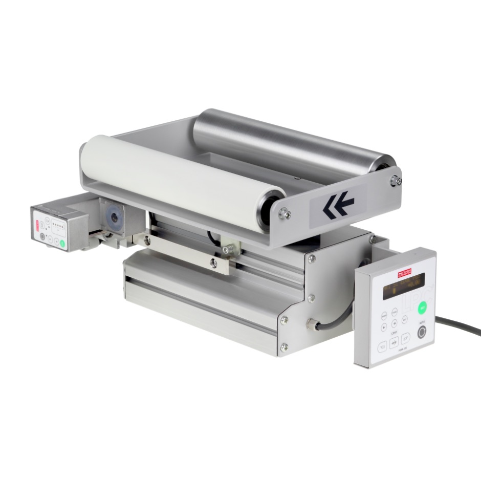
Integrated Miniature Roll Guide
- #Integrated Miniature Roll Guide
Used when carrying out alignment control in the intermediate process of web transport. Due to the built-in controller and sensor, time required for design, installation, wiring and adjustment processes are reduced for the customer, enabling ease of use. With built-in brushless motor, high maintainability, high response and high precision are achieved. It is used for narrow web of 600mm width or less, suitable for alignment control of packaging machines and sanitary goods manufacturing machines.
Drawing


※1: Mounting pitch ※2: Sheet width ※3: External control cable ※4: Sensor cable ※5: Power cable ※6: Mounting nut detailed diagram(S=1/1) ※7: Post-insertion spring nut ※8: Roll height ※9: Dimensions fluctuate according to size
L: Roll surface length Rs: Distance between roll outer diameters Rp: Center-to-center roll distance Lc: Distance to fixed roll Ls: Distance to sensor
※1: Mounting pitch ※2: Sheet width ※3: External control cable ※4: Sensor cable ※5: Power cable ※6: Mounting nut detailed diagram(S=1/1) ※7: Post-insertion spring nut ※8: Dimensions fluctuate according to size
L: Roll surface length Rs: Distance between roll outer diameters Rp: Center-to-center roll distance Lc: Distance to fixed roll Ls: Distance to sensor
Features
- Only connection to the power supply is required, so assembling onto a machine can be completed in a short time.
- Maintenance-free brushless motor is adopted.
- Ball screw-type miniature actuator is built in, enabling the roll frame to rotate powerfully without rattling.
- Turning torque of the roll frame is over 2.5 times that of the conventional gear-type PG-100.
- Coupled with low backlash (less than one-tenth that of a conventional machine), it has a composition which supports the roll frame at 3 points, namely at the pivot axis and 2 points at cam follower, making it a highly rigid roll frame.
- Either IR edge sensor (PSM-75 series) or ultrasonic edge sensor (PSM-46 series) may be selected according to use. Alternatively, by using 2 PSM-75 series units, centering control is made possible.
Specification
| Short Type (PGMW-15-ST) | Long Type (PGMW-15-LT) | ||||||||
| Power supply | DC24V±20% Please connect to the attached cable (5m) terminal. (24V:”+”, 0V:”-”, grounding “FG”) | ||||||||
| Consumption current | 0.6A(supply voltage DC24V) | ||||||||
| Built-in equipment | Controller | PEM-200 | |||||||
| Sensor | Please designate the type and number of sensors. ・PSM-46、46W (maximum 1 unit, edge control) ・PSM-75、75W (maximum 2 units, edge or centering control) When using PSM-75 series, using a dust blow unit to prevent dust attaching to the lens in a dusty environment is effective. The model number is PSM-75W-DB. In such a case, please prepare air pressure :0.2 – 0.5MPa, dry air, maximum consumption 20Nl/min. |
||||||||
| Scope of application | Roll surface length | 150 – 650mm | 200 – 650mm | ||||||
| Roll diameter | φ46 、φ78 Please inquire regarding other specifications. |
||||||||
| Roll materials | ・Aluminum roll (with or without alumite) ・Rubber roll (NBR white) ・CFRP(with or without rubber cork winding) Please inquire about other specifications. |
||||||||
| Roll span | 150mm | 175mm | 200mm | 225mm | 250mm | 275mm | 300mm | 400mm | |
| Correction amount ※1 | ±17mm | ±19mm | ±22mm | ±25mm | ±16mm | ±18mm | ±20mm | ±27mm | |
| Correction speed | 20mm/s | 22mm/s | 25mm/s | 28mm/s | 14mm/s | 15mm/s | 17mm/s | 23mm/s | |
| Maximum web tension ※2 | 200N(web width 250㎜) | 260N(web width 450㎜) | |||||||
| Maximum web running speed | 300m/min | ||||||||
| Operating environment | Temperature:0 – 40 ℃ Humidity:80%Rh or lower (no condensation) | ||||||||
| Mass (excluding drive main body, roll frame) | 4.0kg | ||||||||
| Other | <Method of determining roll frame position> ・Proximity switch is used to set center position and electronic counter-type to set stroke end position(position is set with a controller). Automatically moves to the center when power is turned on (standard specification). ・Proximity switch for stroke end detection may be added as an optional feature. <Position of control panel and connector panel> ・The control panel and connector panel are on the right/left sides of the main drive case. ・The items are shipped in a fixed direction depending on the web flow direction. (Right flow) when the end-side roll in the front, the control panel is on the left side. (Left flow) when the end-side roll in the front, the control panel is on the right side. |
||||||||
※2.Tension is proportionate to the web width.
